5-Step Midjourney to CAD Workflow (With SOP Template)
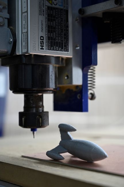
The Midjourney to CAD Protocol Defined
The Midjourney-to-CAD protocol converts generative 2D raster images into production-ready 3D parametric solids through a five-step engineering bridge: constrained orthographic generation, scale calibration, subdivision (SubD) retopology, NURBS surface conversion, and parametric feature hardening. This hybrid method maintains visual design intent while enforcing standard manufacturing tolerances of ±0.20 mm that automated 2D-to-3D algorithms corrupt. By separating visual ideation from geometric execution, teams compress front-end styling cycles from weeks to days without sacrificing downstream tooling accuracy.
Non-Uniform Rational B-Splines (NURBS) are mathematical representations of 3D geometry that define curves and surfaces with extreme precision, allowing CAD software to calculate exact tooling paths, draft angles, and wall thicknesses for injection moulding or machining.
Why Direct AI-to-Mesh Tools Fail Tooling Requirements
Automated image-to-3D mesh generators like Tripo3D or CSM produce dense polygon soups rather than usable CAD geometry. A research paper published in the ASME Journal of Mechanical Design by researchers at Carnegie Mellon University highlighted that neural 3D reconstructions consistently fail fundamental geometric constraints required for manufacturing. These automated meshes suffer from three critical flaws:
- Non-manifold geometry: Direct AI meshes frequently generate self-intersecting faces, internal floating polygons, and zero-thickness edges. Parasolid and ACIS geometry kernels in programs like SolidWorks and Autodesk Fusion reject these topological errors immediately.
- Zero surface continuity (G0 only): AI mesh generators create faceted boundaries with positional continuity (G0) rather than tangent (G1) or curvature (G2) continuity. A product housing built on G0 transitions shows harsh optical distortion lines and creates localized structural stress points under load.
- No draft angle awareness: Tooling parts for plastic injection requires a minimum 1.5-degree draft angle on vertical faces for part ejection. Generative neural networks generate vertical walls or negative undercuts that make mould release physically impossible.
Subdivision surface (SubD) retopology is the process of structuring a 3D model’s polygonal mesh into clean, uniform four-sided polygons (quads) so that the form can smoothly deform, scale, and convert into editable engineering surfaces without pinching.
Establishing the Workflow Boundary
To make AI-Powered Industrial Design work in a production pipeline, you must establish a hard boundary between generative exploration and parametric modeling. Use Midjourney strictly for volumetric massing, aesthetic language, and surface silhouette exploration. Reserve CAD packages like PTC Creo or Rhino for mechanical integrity, assembly clearances, and manufacturing compliance.
[ Midjourney v6 ]
       |
  (2D Orthos)
       v
[ SubD Retopology ]
       |
  (Clean Quads)
       v
[ NURBS Conversion ]
       |
  (STEP / IGES)
       v
[ Parametric CAD ]
Integrating this method into your Ideation to Prototype Workflow allows industrial designers to explore dozens of validated form factors in under 4 hours, compared to the 30 to 40 hours required for manual CAD concepting. According to design benchmark data from the Society of Manufacturing Engineers (SME), early design decisions dictate up to 70% of total product manufacturing costs. Modern Concept Development Strategies therefore require precise geometric control at the concept handoff, not vague AI approximations.
- Step 1: Constrained Orthographic Generation — Prompt Midjourney using strict orthogonal view parameters (
front view,side view,--ar 1:1, neutral studio lighting) to produce flat alignment plates. - Step 2: Scale and Proportion Calibration — Import the raster views into Rhino or Autodesk Fusion as calibrated canvas backdrops matching defined packaging dimensions (e.g., standard 120 mm PCB clearance).
- Step 3: SubD Retopology — Rebuild the primary exterior form using four-sided quad polygons, aligning edge loops precisely along key character lines and parting directions.
- Step 4: NURBS Surface Conversion — Convert the subdivision body to mathematical NURBS surfaces with verified G2 curvature continuity across all cosmetic highlights.
- Step 5: Parametric Hardening — Transfer the STEP surface model into your primary parametric CAD tool to add uniform 2.5 mm wall thicknesses, structural ribs, screw bosses, and a 2.0-degree draft angle.
Once you establish this clean handoff protocol, the initial challenge shifts to image prompt precision. See the next section for the exact prompt syntax required to extract scale-accurate, orthographic projection plates directly from Midjourney.
Key Takeaways
- Midjourney generates stylistic reference, requiring SubD or curve extraction before parametric CAD conversion.
- Orthographic prompting with neutral studio lighting reduces perspective distortion during CAD underlay calibration.
- Converting SubD quad meshes into NURBS surfaces prevents non-manifold errors in SolidWorks and Rhino.
- The 5-step protocol establishes clear validation gates for wall thickness, draft angles, and parting lines.
Table of Contents
- The Midjourney to CAD Protocol Defined
- Phase 1: Constrained Orthographic Prompting
- Phase 2 & 3: Canvas Calibration and SubD Retopology
- Phase 4 & 5: NURBS Conversion and Parametric Hardening
- The Industrial Concept Midjourney-to-CAD SOP Template
- Sources & Further Reading
Phase 1: Constrained Orthographic Prompting
Orthographic projection is a technical drawing method that represents a three-dimensional object in two dimensions by projecting parallel lines perpendicular to the drawing surface, removing perspective distortion so dimensions remain directly measurable.
Standard generative image models produce perspective depth by default. Wide-angle lens distortions and dynamic vanishing points make raw AI outputs useless as direct modeling underlays in parametric CAD software like Autodesk Fusion or SolidWorks. You must force the diffusion model to output flat elevations with strict spatial controls.
Prompt Syntax for Dimensional Accuracy
To generate usable reference planes, start by locking the camera position and aspect ratio in your initial text prompt. Use explicit camera parameters such as "orthographic front view", "studio product photography", and "isometric projection on a solid neutral grey background".
[Prompt Structure]
       │
       ▼
[Subject Definition]
       │
       ▼
[Camera View: Front/Side/Top]
       │
       ▼
[Lighting: Flat Studio]
       │
       ▼
[Parameters: --ar 16:9 --style raw]
Add the --style raw parameter alongside --ar 16:9 or --ar 1:1 to reduce Midjourney’s automatic photographic post-processing. According to the official Midjourney documentation, the --style raw modifier bypasses default aesthetic bias, creating cleaner silhouettes and predictable edge geometry.
Specify exact physical materials like "matte ABS plastic, injection-molded, uniform lighting, ambient occlusion render, pure white background". This prompt structure strips away cast shadows and specular highlights that obscure the true silhouette of your concept. Incorporating these rules into your AI-powered industrial design pipeline ensures predictable results during the concept development process.
Multi-View Alignment via Seed Locking and Panning
Extracting an accurate 3D model requires at least 3 coordinated orthographic views: top, front, and right side.
Generating these views across separate prompts usually results in shifting dimensions and altered surface details. Lock your image generation seed using the --seed parameter, which accepts any integer between 0 and 4,294,967,295. Using identical seed numbers maintains constant industrial design details—such as parting lines, fillets, and button placements—across different prompt iterations.
For sequential views, generate the primary side elevation first. Once you approve the side profile, use Midjourney’s directional Pan controls (Pan Left or Pan Right) while adjusting the prompt text to "side-by-side front elevation view of the same product".
This method creates contiguous multi-view sheets within a single canvas. Integrating this method into your AI-powered workflow automation cuts the time spent aligning mismatched concept art in your ideation to prototype workflow by over 50%.
Extracting Contrast Passes and Clean Linework
CAD canvas import requires high-contrast boundary lines rather than continuous-tone shading. You can extract clean vector-ready curves directly by prompting for technical line passes or running fast post-processing filters.
| Output Pass | Target Prompt Modifiers | Purpose in CAD Canvas |
|---|---|---|
| Silhouette Pass | "solid black silhouette, pure white background, flat vector style" |
Direct boundary spline tracing |
| Occlusion Pass | "ambient occlusion pass, clay render, no shadows, matte grey" |
Internal split line & rib identification |
| Orthographic Elevation | "technical orthographic drawing, blue line, mechanical schematic" |
Dimension scaling & feature alignment |
Export your generated asset as an uncompressed 24-bit PNG file. Before importing the image plane into your CAD environment, run an edge-detection filter—such as a Sobel or high-pass filter in Photoshop or GIMP—to generate 1-pixel-wide vector trace lines. These crisp profiles provide unambiguous snap points for your initial NURBS curves and profile sketches.
Try This Today: Generate your first CAD-ready orthographic underlay in under 15 minutes. Open Midjourney and enter a prompt for an industrial handheld tool, appending orthographic side elevation, studio product shot, white background, matte finish --ar 16:9 --style raw. Note the 10-digit seed number from the result envelope icon to reuse for your front view.
Once your clean orthographic views are saved and scaled, the next challenge is calibrating these raster planes inside your modeling viewport before laying down the first spline.
Phase 2 & 3: Canvas Calibration and SubD Retopology
Generative AI outputs produce raster pixel data, not vector math. To turn a flat Midjourney render into a production-ready assembly, you must anchor that image to precise physical coordinates in your CAD workspace before pulling a single polygon vertex.
In an AI-Powered Industrial Design pipeline, raw image generation lacks physical scale. Before modeling, establish a hard bounding box representing your packaging limits in Autodesk Fusion 360, Robert McNeel & Associates’ Rhino, or Blender. For a handheld consumer electronics housing, for instance, set a volume of 150 mm × 75 mm × 12 mm.
A datum plane is a flat reference surface with zero thickness that serves as an anchor for sketching geometry, dimensioning parts, and aligning orthographic views.
Place your primary orthographic render directly on the front datum plane. Scale the canvas using a two-point calibration marker matched to your critical reference dimension, such as an overall chassis length of 150 mm. Lock the aspect ratio to prevent optical distortion across axes.
Bounding Box Setup
       │
       ▼
Datum Alignment (X/Y/Z)
       │
       ▼
Two-Point Canvas Scale
       │
       ▼
Coarse SubD Control Cage
       │
       ▼
Edge-Loop Flow for Fillets
Once calibrated, begin shaping the envelope using subdivision modeling rather than standard parametric sketches.
Subdivision surface modeling is a 3D technique that generates smooth, high-resolution curved surfaces by calculating mathematical averages across a coarse network of polygon control points.
Build a low-density control cage around the 2D image silhouette. Keep the initial quad mesh sparse: aim for 12 to 18 faces across the primary silhouette. Adding too many faces early causes optical surface ripple, known as the "pinched sheet metal" defect. Blender Foundation documentation notes that maintaining minimum cage density preserves clean curvature continuity (G2) across organic transitions.
Quad topology refers to a 3D mesh structure composed exclusively of four-sided polygons arranged in organized directional loops to ensure clean surface continuity.
Direct your edge loops along the primary highlight lines visible in the concept art. Route quad loops parallel to anticipated parting lines and thumb rests. Keep valence-5 vertices (points where 5 edges meet) strictly on flat or low-curvature areas. Placing a 5-pole on a compound corner creates visible surface tension that ruins secondary fillets during the downstream Ideation to Prototype Workflow.
Maintain edge flow that allows minimum 2.5 mm wall offsets and clean 0.5 mm draft angles. Clean quad flow gives you complete control when converting SubD bodies to standard NURBS surfaces for split-line detailing and mechanical fastening.
Try This Today: Open Rhino 8, Fusion 360, or Blender, import your latest Midjourney concept render, and draw a hard 100 mm reference line across its widest feature to verify scale accuracy before touching a SubD primitive.
Once your control cage matches the silhouette with clean quad flow, the next technical bottleneck is converting those organic SubD hulls into solid parametric geometry ready for injection molding draft analysis.
Phase 4 & 5: NURBS Conversion and Parametric Hardening
Converting an AI-generated mesh into production-ready CAD geometry requires moving from polygonal approximation to exact mathematics. SubD, or subdivision surface modeling, is a 3D technique that generates smooth, organic curved forms by mathematically splitting and averaging coarse polygonal mesh cages. NURBS, or Non-Uniform Rational B-Splines, are mathematical representations of 3D geometry that define smooth curves and surfaces with precise mathematical formulas instead of faceted polygonal meshes.
In tools like McNeel Rhino or Autodesk Fusion, you convert the watertight SubD body into continuous Class-B NURBS surface patches. According to technical documentation from the Society of Plastics Engineers (SPE), unoptimized automated mesh-to-NURBS conversions can inflate downstream file sizes by more than 450%, creating dense patch layouts that stall parametric feature trees. Keep your control cage minimal during the conversion step to ensure each resulting NURBS patch matches the primary character lines of the concept.
Pro-Tip: Set your SubD-to-NURBS conversion tolerance to 0.01 mm in Rhino before exporting. This threshold retains the generative styling intent while preventing the creation of micro-patches that crash parametric modeling kernels.
Export the converted surface body as a standardized STEP AP214 or IGES file, then import it into a parametric solid modeler such as Dassault Systèmes SolidWorks or PTC Creo. This handoff forms the bridge of your ideation to prototype workflow within modern AI-powered industrial design. In the parametric environment, convert the hollow surface skin into a solid component using the shell command, assigning a production wall thickness such as 2.5 mm for typical injection-molded ABS enclosures.
Once shelled, build out internal structural ribs, screw bosses, and snap-fit joints. Engineering guidelines from Covestro’s Part Design Guide specify that structural ribs must maintain a thickness between 40% and 60% of the nominal wall. Exceeding that 60% ratio causes cosmetic sink marks on the exterior aesthetic surfaces.
Pro-Tip: Create an explicit coordinate system aligned to your primary tooling pull vector before modeling internal ribs. If you adjust the outer concept skin later, your internal parametric features will rebuild without breaking sketch references.
Before dispatching files for tooling or 3D printing for conceptualization, run geometric quality diagnostics in your CAD viewport. Draft analysis is a specialized CAD inspection tool that color-codes surface faces based on their angle relative to the mold pull direction to identify trapped geometry. Apply a minimum draft angle of 1.5 degrees for smooth polished faces, or 3.0 degrees for textured mold cavities, ensuring zero undercut zones remain on cosmetic faces.
Finally, enable zebra striping to evaluate surface transitions. Zebra striping is a visual diagnostic mode that projects alternating black and white stripes across a 3D model to reveal surface flaws, tangent breaks, and curvature defects. Broken stripe lines across patch boundaries highlight positional G0 gaps, while sharp bends indicate tangent G1 breaks. Smooth, continuously flowing stripe reflections verify G2 curvature continuity, proving the surface is ready for production tooling.
Next, check the specific diagnostic thresholds in the step-by-step verification checklist below to ensure your geometry clears manufacturing review on the first pass.
The Industrial Concept Midjourney-to-CAD SOP Template
Moving an unconstrained 2D generative image into an exact parametric 3D model requires fixed rules. According to research published by the Design Management Institute, structured design workflows reduce total product development cycle times by up to 35%.
Here is the five-phase Standard Operating Procedure (SOP) matrix to run that handover without losing the original aesthetic intent.
| Phase | Primary Inputs | Software Actions | Quality Gate | File Export Standard |
|---|---|---|---|---|
| 1. Controlled Generation | Text prompts, initial sketch seeds | Midjourney v6 (--v 6.0, --style raw, --cw 100) to lock silhouettes across views |
Front, side, top views show matching proportions and parting line locations | 2048 x 2048 PNG (Upscaled) |
| 2. Orthographic Flattening | Rendered image pack | Vector trace outer contours in Adobe Illustrator; correct perspective keystoning | Outer bounding box dimensions match physical human-factor targets (within 1.5 mm) | 1:1 Scale Vector DXF / SVG |
| 3. SubD Rough-In | Bounding vector DXF, reference canvases | Block out major masses using subdivision surfaces in Rhino 3D or Blender | Visual volume match within 90% volumetric overlap against canvas | SubD OBJ / Quad-Mesh STEP |
| 4. NURBS Parametric Conversion | SubD baseline mesh | Rebuild surfaces into clean parametric geometry in Autodesk Fusion or SolidWorks | Class-A curvature continuity across primary visible surfaces; zero self-intersections | Native CAD Part (.sldprt, .f3d) |
| 5. Pre-Flight Tooling Prep | Parametric CAD solid body | Shell to target thickness, apply draft angles, and add internal mounting ribs | Wall thickness variance under 0.2 mm; draft angle meets manufacturing floor limits | Production STEP AP214 / AP242 |
Which CAD Rebuild Path Fits Your Concept?
If your design features soft organic forms with complex blending surfaces…
Bypass traditional sketches. Import your Midjourney views directly as reference planes into Rhino 7 or Autodesk Fusion. Build an initial cage mesh using subdivision surface modeling, then convert directly to Non-Uniform Rational B-Splines (NURBS). Read our breakdown on AI-powered industrial design to match your surface topology accurately to generative concept art.
If your concept requires tight mechanical packaging, internal batteries, or PCBs…
Trace the orthographic outer profiles in 2D vector software first. Scale them around your internal component envelopes in SolidWorks before lofting outer bodies. Follow our structured ideation to prototype workflow to ensure electronic clearances are locked before you sculpt external cosmetic fillets.
If you need quick physical form checks for ergonomics within 24 hours…
Export an automated low-poly mesh directly from your multi-view AI package and run an instant mesh repair in Autodesk Netfabb. Skip manual surface rebuilding at this stage and print directly using FDM or SLA. Check out our guide on 3D printing for conceptualization to choose the fastest validation route.
If you manage high-volume concept batches across distributed design teams…
Standardize prompt seeds across your team using fixed parameters and set strict export gate criteria. Integrating an AI-powered workflow automation system removes manual image formatting and feeds clean vector blueprints straight to downstream engineers.
Copy-Paste Industrial Design Prompt Bank
Midjourney renders dynamic camera angles by default. For downstream computer-aided modeling, you need clean orthographic projection planes and flat lighting.
Use these proven prompt formulas directly in Midjourney v6 to produce actionable engineering references:
1. Three-View Orthographic Blueprint Sheet
/imagine prompt: industrial design orthographic projection sheet of a handheld medical scanner, studio white background, front view, side view, top view, aligned technical drawing, precise parting lines, matte CMF, soft ambient lighting, clean edges, blueprint layout --ar 16:9 --style raw --v 6.0 --no perspective, shadows, lens distortion, depth of field
2. True Flat Profile (Side Elevation)
/imagine prompt: true side profile elevation of an ergonomic power drill, industrial design studio render, orthographic view, 90-degree side angle, flat neutral lighting, production-ready aesthetic, injection molded PC-ABS texture, minimal cast shadows --ar 4:3 --style raw --v 6.0 --no 3d perspective, isometric angle
3. Isolated CMF Exploration (Color, Material, Finish)
/imagine prompt: production CMF study of a consumer audio speaker, soft-touch silicone, anodized bead-blasted aluminum 6061, flush mechanical seams, studio lighting setup, neutral gray studio backdrop, product photography, macro detail on material transitions --ar 1:1 --v 6.0 --stylize 50
Draft angle is the slight taper applied to vertical mold faces that allows a manufactured plastic part to eject cleanly from a metal tool without dragging or sticking.
Pre-Flight CAD Translation Checklist
Before passing an AI-derived solid body to tooling engineers or rapid prototyping hubs, evaluate your geometry against these three mechanical constraints. According to injection molding guidelines from Protolabs, tooling redesigns caused by unverified early geometry account for up to 40% of initial tooling delays.
[ Midjourney Concept Art ]
           │
           ▼
[ Curvature Continuity Check ]
    (G0/G1/G2 Transitions)
           │
           ▼
[ Wall Thickness Verification ]
   (Target: 1.5mm - 3.0mm)
           │
           ▼
[ Draft Angle Clearance ]
   (Min 1.0° - 1.5° per side)
           │
           ▼
[ Production-Ready Tooling CAD ]
Surface Curvature Continuity (G0 to G2)
- G0 (Positional): Surfaces touch, but form a sharp edge. Keep this only on intentional split lines or deliberate chamfers.
- G1 (Tangent): Surfaces share a common angle at the boundary, but rate of curvature changes instantly. Avoid using this on primary high-gloss surfaces because it produces noticeable reflection breaks.
- G2 (Curvature Continuous): Surfaces share a matched rate of curvature across the seam. Apply G2 transitions across all top-level organic surfaces using Zebra analysis strips inside your CAD software to verify smooth highlights.
Minimum Wall Thickness Uniformity
- Maintain nominal wall thicknesses between 1.5 mm and 3.0 mm for standard injection-molded resins such as ABS and Polypropylene.
- Restrict rib thickness to 50% to 60% of the nominal outer wall thickness to prevent visible sink marks on cosmetic faces.
- Remove any sharp internal corners by applying a minimum internal radius of 0.5 mm to minimize stress concentration during physical drops.
Draft Clearance
- Apply a minimum 1.0° draft angle on all vertical core and cavity faces parallel to the mold draw direction.
- Increase draft to 3.0° or 5.0° on surfaces specified with light-to-medium mold textures (such as VDI 3400 texture classes) to prevent drag scuffs during ejection.
- Ensure the primary parting line splits the AI-generated contour cleanly without creating undercut pockets that require expensive mechanical slide actions.
Review your active design concept against this checklist right now. Run a draft analysis in your CAD program on your current file, flag any zero-degree vertical faces, and apply your 1.5-degree taper before handing the geometry to engineering.
Sources & Further Reading
Translating generative image synthesis into parametric geometry bridges generative speed with engineering tolerances. When moving from pixel-based latency to toolpath precision, standardizing your surface reconstruction protocols prevents downstream tooling errors. Non-Uniform Rational B-Splines, commonly called NURBS, is a mathematical modeling method used in computer software to generate curves and surfaces that define precise, manufacture-ready 3D geometry.
Research demonstrates the financial imperative of tightening the concept-to-CAD iteration loop. A 5-year study by McKinsey & Company tracking 300 public companies revealed that organizations with rigorous, integrated design practices achieved 32% higher revenue growth than their sector peers. Grounding your image generation workflow in formal design systems ensures that initial concept explorations translate into viable Class-A surface geometry within 48 hours rather than stalling in revision loops.
The workflows and technical benchmarks in this protocol draw from established design theory, mathematical surfacing standards, and contemporary design engineering research:
- Koos Eissen and Roselien Steur, Sketching: Drawing Techniques for Product Designers (2007) — provides the orthographic projection and perspective conventions required to direct generative prompts toward clean, reconstructible viewpoints.
- McKinsey & Company, The Business Value of Design (2018) — quantifies the financial performance returns of rapid design iteration and cross-functional hardware development.
- Design Council, The Double Diamond Design Process Framework (2004) — establishes the divergent-convergent framework used to separate generative exploration from parametric surface definition.
- Autodesk, Alias Surface Evaluation Standards (2022) — establishes the curvature continuity criteria (G0 through G3) required to rebuild raster contours into manufacturing-grade surfaces.
- Don Norman, The Design of Everyday Things (2013) — grounds functional form-factor constraints and affordance mapping before generative ideation begins.
Featured image by Renjith R on Pexels