Additive Manufacturing for Creative Design (Framework)
⏱ 16 min read
Additive manufacturing enables creative designers to fabricate geometries that are physically impossible with subtractive tooling, converting algorithmic code directly into physical parts without tooling delays. By constructing components layer by layer, it dissolves traditional cost penalties associated with aesthetic complexity, consolidates multi-part assemblies into monolithic units, and produces functionally graded materials on demand. Creative teams can now test functional, human-scale prototypes within 24 hours rather than waiting six weeks for conventional tooling.
Key Takeaways for Design Leaders
- Complexity Is Free: Tooling constraints vanish; internal lattices, conformal cooling passages, and undercut geometries incur zero additional tooling expense.
- Direct Digital Fabrication: Transitioning from CAD models to physical objects compresses iteration cycles from weeks to hours, allowing daily tangible design reviews.
- Assembly Consolidation: Multi-part mechanisms merge into single-build assemblies, reducing fastener counts, part numbers, and failure points.
- Mass Customization: Parametric inputs adapt individual parts directly to user anatomy or architectural spaces with zero retooling costs.
Table of Contents
- Additive Manufacturing Methods and Creative Design Capabilities
- Geometrical Complexity and Biomimetic Aesthetics in Physical Products
- Creative Applications Across Fashion, Architecture, and Industrial Art
- End-to-End Design Workflow From CAD to Post-Processing
- Strategic Production Trade-Offs, Economics, and Material Sustainability
- Systematic Evaluation Protocol for Creative Additive Projects
- Sources & Further Reading
Additive Manufacturing Methods and Creative Design Capabilities
Additive manufacturing joins materials layer by layer to make physical objects from 3D model data, as codified by the ISO/ASTM 52900 standard. Subtractive methods mill stock away or cast material into high-pressure molds. Additive builds place polymer, metal, or ceramic exclusively where structural or aesthetic needs require it. This mechanism eliminates the draft angles, parting lines, and tool-access clearances demanded by Computer Numerical Control (CNC) milling and injection molding.
Four primary process categories dominate creative production workflows:
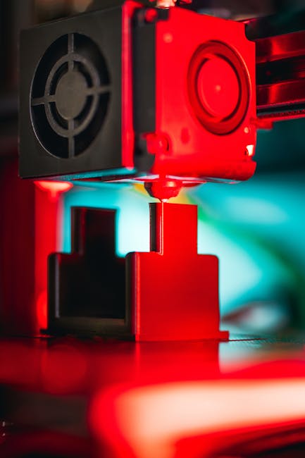
- Material Extrusion (Fused Deposition Modeling / FDM): Spools of thermoplastic filament like PLA, ABS, or PETG feed through a heated nozzle onto a build plate. Layer heights typically range from 100 to 300 microns. It provides an accessible, low-cost baseline for rapid form checks, ergonomic testing, and rough volumetric visualization.
- Vat Photopolymerization (Stereolithography / SLA & DLP): Liquid photopolymer resins cure under precise ultraviolet laser or digital light projector exposure. SLA achieves fine feature resolution down to 25-micron layer heights. It produces smooth surface finishes suitable for castable jewelry masters, optical prototypes, and dental aligners.
- Powder Bed Fusion (Selective Laser Sintering / SLS & Direct Metal Laser Sintering / DMLS): High-powered CO2 or fiber lasers sinter powdered Nylon (PA11, PA12) or metal alloys (titanium, stainless steel, aluminum) layer by layer. Unfused powder supports the part during the build cycle, eliminating sacrificial support structures and unlocking complete overhang freedom. Teams comparing these outputs often consult our PolyJet vs DMLS fits worked tolerancing chart.
- Material Jetting (PolyJet & Multi Jet Fusion / MJF): PolyJet systems deposit microscopic droplets of photopolymer resin cured instantly with UV lamps, blending rigid and elastomeric polymers in a single pass. HP’s Multi Jet Fusion applies fusing and detailing agents across a powder bed, delivering isotropic mechanical strength at speeds up to 10 times faster than point-laser sintering systems.
Pro-Tip: Creative teams frequently misapply subtractive CAD intuition to additive printers. Emphasizing organic forms and internal weight reduction rather than uniform wall thicknesses allows design teams to explore fresh ideas. This technique aligns with the creative protocols found in Unlock Your Genius: Master Edward De Bono’s Creative Thinking Methods.
Iterative cycle time is the primary competitive metric in modern design studios. Where traditional tooling demands 6 to 12 weeks of lead time before the first physical test part emerges, additive hardware outputs functional samples in 14 hours. Early aviation pioneers refined airfoils through rapid, physical experimentation, a dynamic explored in The Wright Brothers’ Secret: Iterative Design & Engineering Innovation That Took Flight. Physical artifacts allow designers to test tactile reactions immediately using methods outlined in Usability Testing: The Human-Centric Design Secret Weapon, ensuring that ergonomics match human needs early in development.
🧩 Puzzle: The Unmachinable Whistle
An industrial designer delivers an STL file for a one-piece pea whistle. It has a rigid, solid spherical bead trapped entirely inside a hollow, enclosed acoustic chamber. The outer shell has three narrow air slots, none larger than 2 mm wide. The bead inside is a solid 8 mm diameter sphere. The whistle must emerge from the manufacturing equipment ready to blow, with no assembly, gluing, or secondary fastening. Can this object be manufactured using traditional CNC milling or multi-cavity injection molding?
Reveal the answer
Answer: Neither CNC milling nor injection molding can fabricate this whistle as a single component. Subtractive tooling cutters cannot penetrate the 2 mm slots to carve an 8 mm spherical bead out of solid material, and injection mold cores cannot extract through narrower apertures after resin cools.
Thinking Move: Inversion of Fabrication Constraints. Additive manufacturing builds the internal bead and exterior shell simultaneously layer by layer. In Powder Bed Fusion (SLS), unbonded powder surrounds the bead during printing, and the operator shakes out the loose media through the air slots during post-processing, leaving the captive bead fully functional inside.
Geometrical Complexity and Biomimetic Aesthetics in Physical Products
Additive manufacturing treats geometric complexity as economically neutral. In machining, cutting a pocket adds cycle time, tool wear, and operator expense. In additive systems, building a lattice or hollow pocket consumes less raw powder and takes less laser exposure time than printing a solid block. This inversion allows designers to incorporate filigree, triply periodic minimal surfaces (TPMS), and gyroid structures into daily projects.
Biomimicry moves from concept sketches into functional components through these methods. Bone structures optimize strength through porous cancellous scaffolding surrounded by dense cortical outer walls. Using generative algorithms, designers mirror these natural forms in seating, lighting structures, and hardware enclosures. Form matches mechanical function in a balanced manner, echoing architectural principles detailed in Universal Design: The Unseen Innovation Spark in Architecture.
Tactile variation within a single uninterrupted component is now practical. Multi-material systems combine rigid polymers with Shore 20A to 85A elastomers in single builds, creating soft-touch grips over stiff internal skeletons without separate adhesive steps. Design teams can construct profiles that match specific user hand sizes using techniques from User Persona Development for Creative Solutions. Incorporating ergonomic research early guarantees that surface variations improve grip and utility.
Algorithmic optimization software automates this balance. Finite Element Analysis (FEA) strips material from low-stress zones while thickening load-bearing lines. Generative systems produce organic shapes reminiscent of muscle sinew or branching trees. Designers often apply systematic problem-solving rules, such as those found in TRIZ principles for creative problem-solving, to resolve engineering trade-offs. To systematically cut unneeded features, teams also use the TRIZ Trimming: Component Pruning Matrix. Digital coordination transforms production floors into flexible fabrication hubs, as discussed in The Role of AI in Designing Smart Factories.
FAQ: How does additive manufacturing enable biomimetic design?
Additive manufacturing deposits material strictly along designated stress paths without requiring tool retraction paths or mold draft angles. This capability enables designers to produce internal cellular matrices, variable-density infills, and branching vascular networks that mimic bone, wood, and coral. Such organic geometries deliver exceptional strength-to-weight ratios and natural fluid dispersion, fulfilling core methods in Unlock Innovation: Your Ultimate Guide to the Design Thinking Process.
FAQ: What are the functional implications of multi-material printing?
Multi-material jetting blends materials with different mechanical, thermal, and visual properties in a single print head cycle. Designers can print flexible hinges, transparent lenses, shock-absorbing elastomers, and rigid structural ribs directly into one component. This eliminates secondary fasteners, reduces assembly labor, and improves durability. Teams validate these physical prototypes using practical methods in Usability Testing: The Human-Centric Design Secret Weapon.
Creative Applications Across Fashion, Architecture, and Industrial Art
Creative industries deploy additive systems to break standard manufacturing constraints, producing bespoke garments, monumental installations, and responsive consumer products.
Fashion designers combine digital modeling with material deposition to craft bespoke garments and footwear. Dutch designer Iris van Herpen uses selective laser sintering and stereolithography to produce gowns that replicate water ripples and bird plumage. Footwear brands like Adidas, through their 4DFWD platform, use Carbon’s Digital Light Synthesis (DLS) to print lattice midsoles. These soles compress forward under vertical pressure, converting downward impact into forward momentum across 5 million mechanical testing cycles.
Jewelry artisans use vat photopolymerization with castable wax resins to manufacture items with thin prongs, undercuts, and nested components. Jewelers print master patterns within 4 hours, encase them in ceramic investment slurry, burn out the resin cleanly at 730°C, and vacuum-cast platinum or 18k gold directly into the void. This technique bypasses rubber molds and enables customized items like signet rings with personal topographic scans.
Architects and interior designers fabricate structural panels, modular facade components, and detailed scale models. In Zurich, ETH researchers used 3D sand-printing to cast the “Smart Slab,” an 80-square-meter concrete ceiling that is 70% lighter than standard slabs. Parametric wall claddings incorporate custom acoustic cavities that dampen specific vocal reverberation frequencies, bridging architectural aesthetics with Universal Design: The Unseen Innovation Spark in Architecture.
Industrial design teams use additive hardware to accelerate feedback loops. Rather than waiting weeks for third-party prototypes, designers 3D-print multiple handle variants overnight, verify them in morning meetings, and iterate before lunch. This rapid pace mirrors the steps outlined in Unlock Innovation: Your Ultimate Guide to the Design Thinking Process and the disciplined testing described in The Wright Brothers’ Secret: Iterative Design & Engineering Innovation That Took Flight. Teams assessing design risk can also use the Creative Risk Rubric for Design Portfolios to balance novelty against manufacturability.
Large-scale public art studios use wire arc additive manufacturing (WAAM) to weld complex metal sculptures from stainless steel or bronze without formwork. The MX3D bridge in Amsterdam spans 12 meters across the Oudezijds Achterburgwal canal, welded using multi-axis industrial robots. Sculptors merge electronics directly into printed voids, generating interactive installations that adapt to environmental changes and prompting creators to Start Thinking Of Yourself As A Creative Person.
Automotive designers use powder bed fusion to print bespoke performance parts. Porsche 3D-prints custom bucket seats with adjustable lumbar support tailored to driver body scans. Aerospace engineers consolidate 855 separate parts into 12 functional sub-assemblies inside the GE Catalyst turboprop engine, reducing weight by 5% and cutting fuel burn by 20%. These engineering methods draw on TRIZ principles for creative problem-solving to solve physical trade-offs.
Pro-Tip: Tailoring products to individual users demands explicit requirements. Building detailed user models using User Persona Development for Creative Solutions prevents studios from adding complex features that confuse the customer.
Design teams can evaluate project viability using our 10-Point Novelty vs Feasibility Audit before ordering expensive production runs. Additive processes also reduce industrial waste and support sustainable practices, as detailed in Sustainable Product Design Innovation.
🃏 Draw a card: Creative Geometry Prompts
Pick a number before you peek — no rerolls.
Card 1
Replace two intersecting walls with an interconnected gyroid lattice that cuts part weight by 40% while preserving torsional rigidity.
Card 2
Incorporate internal fluid passages directly into the structural ribbing to regulate thermal expansion without external cooling tubes.
Card 3
Replace separate screw fasteners and snap tabs by printing the hinge pins and mechanical clips directly into the housing as a pre-assembled unit.
Card 4
Vary wall thickness gradually from 0.8 mm to 3.5 mm along the primary load line to distribute mechanical strain naturally.
Card 5
Embed micro-texture patterns onto tactile touchpoints to provide ergonomic grip without secondary silicone overmolding.
Card 6
Consolidate a multi-material enclosure into a single-step build by assigning Shore 40A elastomer to flex zones and rigid nylon to load-bearing areas.
End-to-End Design Workflow From CAD to Post-Processing
Modern additive workflows link digital geometry directly to machine toolpaths through a structured five-stage pipeline: parametric modeling, mesh repair, print orientation, build execution, and surface post-processing.
Designers start with solid modeling CAD suites (SolidWorks, Autodesk Fusion 360, PTC Creo), polygon sculpting tools (ZBrush, Blender), or parametric engines (Grasshopper for Rhino). Generative tools use physics engines to distribute material along calculated stress paths. This analytical step bridges structural design with systems detailed in The Role of AI in Designing Smart Factories. Before transferring files downstream, engineers map customer needs to technical constraints using the House of Quality QFD.
File formats impact final surface accuracy. The legacy STL format converts curved surfaces into planar triangles, losing curved tolerances unless file sizes become unwieldy. The open 3MF (3D Manufacturing Format) standard replaces legacy files by embedding full polygon color, multi-material boundaries, interior lattices, and licensing data within a single compressed archive. Teams must eliminate self-intersecting meshes, non-manifold edges, and reversed surface normals using slicing software like Ultimaker Cura, PrusaSlicer, or Materialise Magics before sending jobs to the machine.
Design for Additive Manufacturing (DfAM) requires strict adherence to physical limits:
- Minimum Wall Thickness: Maintain a minimum 0.8 mm for FDM, 0.4 mm for SLA, and 0.6 mm for SLS to prevent layer collapse during printing.
- Self-Supporting Angles: Design overhangs at 45 degrees or steeper relative to the build plate. Surfaces exceeding 45 degrees require sacrificial support columns, which increase material consumption and post-processing touch labor.
- Powder Escape Orifices: Powder bed fusion processes require at least two 4 mm escape holes on opposite sides of hollow cavities to drain unfused powder.
Engineers combine systematic problem-solving rules from TRIZ principles for creative problem-solving to navigate these geometric constraints. Teams also use Inclusive Design Principles: Creating Products for Everyone to guarantee that final products suit users with varying motor capabilities.
Rapid iteration speeds project velocity. Designers inspect physical builds, note clearance errors, refine the digital mesh, and run new tests within 24 hours. This cadence reflects the iterative methods examined in The Wright Brothers’ Secret: Iterative Design & Engineering Innovation That Took Flight and the user feedback steps in Unlock Innovation: Your Ultimate Guide to the Design Thinking Process. Effective iteration flourishes in environments with high Psychological Safety: The Rocket Fuel for Your Boldest Creative Risks, where teams treat print failures as essential data, recognizing The Psychology of Failure in Creative Processes as part of technical innovation. Project leads can structure these fast cycles using the Creative Spike Charter.
Pro-Tip: Anchor your design parameters in target user needs before adjusting slicer settings. Setting up clear personas with User Persona Development for Creative Solutions keeps your team focused on valuable features rather than aesthetic novelties.
Post-processing finishes the raw build. Techniques vary depending on the chosen technology:
- Support Removal: Break away mechanical support columns using micro-cutters, or dissolve soluble PVA/breakaway supports in ultrasonic water baths.
- Surface Smoothing: Sand surfaces mechanically through 220 to 1200 grit abrasives, or expose parts to vaporized solvents like ethyl acetate or acetone for 15 seconds to smooth outer layer steps.
- Dyeing and Sealing: Immerse porous SLS Nylon components into heated water-based acid dye baths at 60°C for 30 minutes to achieve uniform deep pigmentation.
- Thermal Annealing: Heat-treat high-performance polymers (PEEK, ULTEM) at 150°C to relieve internal layer stresses and boost overall tensile strength.
Once post-processing is complete, engineers run functional validation trials, using guidelines from Usability Testing: The Human-Centric Design Secret Weapon to verify physical dimensions and ergonomic balance.
Strategic Production Trade-Offs, Economics, and Material Sustainability
Additive manufacturing is not a universal substitute for mass-production injection molding or sheet metal stamping. Design teams evaluate technical constraints, unit economics, digital intellectual property risks, and environmental lifecycle metrics before selecting an additive production route.
Self-Assessment: Additive Manufacturing Readiness
Assess your current design and production practices across these five practical criteria:
Scoring Guide:
- 0-2 Checks: Standard manufacturing methods remain your best path. Tooling-free additive workflows will add per-unit costs without delivering clear functional benefits.
- 3-4 Checks: High additive potential. Consolidate your assemblies and verify build tolerances using our PolyJet vs DMLS fits chart.
- 5 Checks: Ideal additive business case. Fast-track your prototype by using the Creative Spike Charter to organize build trials.
Traditional manufacturing requires substantial capital upfront. An injection mold for a complex electronics enclosure costs between $30,000 and $70,000 and takes 10 weeks to cut from tool steel. Additive manufacturing requires zero upfront tooling. However, the marginal cost per part remains flat regardless of volume. When production exceeds 10,000 units, injection molding delivers lower total costs due to cycle times of 15 seconds per shot, compared to 12 hours for an additive build plate. Early-stage startups managing capital across these options can find guidance in Seed Funding for Creative Startups.
| Evaluation Vector | Injection Molding / CNC Milling | Industrial Additive Manufacturing |
|---|---|---|
| Upfront Capital Expenditure | $15,000 – $100,000+ for hard steel tooling and fixtures. | $0 dedicated tooling expense; low barrier to initiate production runs. |
| Per-Unit Marginal Cost | Very low ($0.50 – $4.00 per part at volume). | Moderate to high ($15.00 – $250.00+ based on mass, build volume, and machine run hours). |
| Geometric Flexibility | Restricted by draft angles, cutter reach, and parting lines. | Supports freeform undercuts, internal voids, conformal channels, and triply periodic lattices. |
| Lead Time to First Article | 6 to 14 weeks for tool fabrication, T1 samples, and adjustments. | 6 to 24 hours directly from sliced geometric mesh files. |
| Direct Material Waste | High subtractive waste (up to 80% scrap metal swarf in aerospace milling). | Low net material use; unfused SLS powder reclaims at 50% to 70% ratios. |
Intellectual property protection is an active concern when deploying digital manufacturing workflows. Once an engineer uploads an unencrypted STL or STEP file, recipients can reproduce the part on any compatible machine without oversight. Industrial teams use secure edge-slicing networks and cryptographic license keys embedded directly into G-code files. Studios should establish clear IP ownership boundaries using frameworks from our Patent vs Trade Secret Decision Matrix.
Environmental trade-offs require careful evaluation. Additive systems reduce raw material waste by placing resin or filament strictly along functional paths, avoiding the heavy swarf waste typical of CNC machining. Unfused SLS nylon powder blends with virgin resin at refresh ratios between 50:50 and 70:30. Scrap materials and spent powder can be reused using the Scrap-to-Product Matrix. However, printers draw steady electrical power throughout lengthy print cycles, and photopolymer resins require dedicated hazardous waste disposal. Designers prioritize sustainable practices as detailed in Sustainable Product Design Innovation and evaluate circular life cycles using the Circular Product Disassembly Audit.
On-demand production transforms traditional supply chains. Instead of warehousing thousands of spare components, companies maintain digital inventories and print replacement parts on demand. This approach eliminates inventory holding costs, supports Inclusive Design Principles: Creating Products for Everyone through custom adaptations, and relies on rigorous testing protocols from Usability Testing: The Human-Centric Design Secret Weapon. Adopting this digital mindset encourages creators to Start Thinking Of Yourself As A Creative Person.
Systematic Evaluation Protocol for Creative Additive Projects
Design teams should run this four-step evaluation before ordering production hardware or commissioning expensive contract runs:
Design for Additive Manufacturing (DfAM) Production Protocol
1. GEOMETRY SCREENING:
   [ ] Confirm presence of complex features impossible with CNC/molding (undercuts, lattices, internal channels).
   [ ] Target minimum wall thickness: >= 0.8 mm (FDM) | >= 0.4 mm (SLA) | >= 0.6 mm (SLS/MJF).
   [ ] Orient overhangs >= 45 degrees to minimize support structures.

ASSEMBLY CONSOLIDATION REVIEW:
 Identify adjacent parts for monolithic consolidation. Target: >= 30% fastener reduction.
 Check captive clearances: maintain minimum 0.4 mm gap between interlocked moving components.
 Add two 4 mm escape holes for hollow geometries to drain unfused media.

ECONOMIC VOLUME CALCULATOR:
 Forecast production: if > 5,000 units, compare tooling amortisation against per-unit print fees.
 Calculate build volume density: pack parts efficiently within the machine build envelope.
 Factor post-processing labor (support removal, bead blasting, dyeing) into unit costs.

MATERIAL VERIFICATION & TESTING:
 Select polymer or metal matched to load, temperature, and environmental exposure.
 Print test artifacts to verify directional tensile strength along the build axis (Z-axis).
 Validate dimensional tolerances using coordinate measuring machines before production sign-off.
Creative directors and engineering leads balance aesthetic vision with physical manufacturing limits. Additive manufacturing turns complex geometry into a cost-effective design choice, giving teams the freedom to create lighter, stronger, and more personalized physical products.
Sources & Further Reading
- Gibson, Ian, David Rosen, and Brent Stucker. Additive Manufacturing Technologies: 3D Printing, Rapid Prototyping, and Direct Digital Manufacturing. 3rd ed., Springer, 2021.
- Wohlers Associates. Wohlers Report 2023: 3D Printing and Additive Manufacturing State of the Industry. Wohlers Associates, 2023.
- International Organization for Standardization. ISO/ASTM 52900:2021 Additive manufacturing — General principles — Fundamentals and vocabulary. ISO, Geneva, 2021. https://www.iso.org/standard/74514.html
- Oxman, Neri. “Material Ecology.” Architectural Design, vol. 80, no. 2, 2010, pp. 42–47.
- Diegel, Olaf, Axel Nordin, and Damien Motte. A Practical Guide to Design for Additive Manufacturing. Springer, 2020.
Featured image by Jakub Zerdzicki on Pexels